Show Posts

This section allows you to view all posts made by this member. Note that you can only see posts made in areas you currently have access to.


Topics - mark

Pages: [1] 2 3 ... 19
1
Hi All

This example shows how to configure a peripheral pin with help if the _CONFIG_PERIPHERAL() or _CONFIG_PERIPHERAL_LOOPBACK() macros.

As an example I will configure LPSPI3_SCK function on the pin referenced as GPIO_AD_B1_15 (assuming an i.MX RT 106x)


This is the code:

IOMUXC_LPSPI3_SCK_SELECT_INPUT = IOMUXC_LPSPI3_SCK_SELECT_INPUT_GPIO_AD_B1_15_ALT2;
_CONFIG_PERIPHERAL_LOOPBACK(GPIO_AD_B1_15, LPSPI3_SCK, (IOMUXC_SW_PAD_CTL_PAD_PKE | IOMUXC_SW_PAD_CTL_PAD_SPEED_MEDIUM | IOMUXC_SW_PAD_CTL_PAD_DSE_6));


and this is how one arrives at it:

1. One needs to know which GPIO reference (PAD) it is on -> GPIO_AD_B1_15 in this case

2. One searches for this in iMX.h until one finds the list of mux options belonging to it

    #define GPIO_AD_B1_15_FLEXSPIA_SS0_B           (IOMUXC_SW_MUX_CTL_PAD_MUX_MODE_ALT0)
    #define GPIO_AD_B1_15_ACMP_OUT03               (IOMUXC_SW_MUX_CTL_PAD_MUX_MODE_ALT1)
    #define GPIO_AD_B1_15_LPSPI3_SCK               (IOMUXC_SW_MUX_CTL_PAD_MUX_MODE_ALT2)
    #define GPIO_AD_B1_15_SAI1_TX_SYNC             (IOMUXC_SW_MUX_CTL_PAD_MUX_MODE_ALT3)
    #define GPIO_AD_B1_15_CSI_DATA02               (IOMUXC_SW_MUX_CTL_PAD_MUX_MODE_ALT4)
    #define GPIO_AD_B1_15_GPIO1_IO31               (IOMUXC_SW_MUX_CTL_PAD_MUX_MODE_ALT5)
    #define GPIO_AD_B1_15_USDHC2_DATA7             (IOMUXC_SW_MUX_CTL_PAD_MUX_MODE_ALT6)
    #define GPIO_AD_B1_15_KPP_COL00                (IOMUXC_SW_MUX_CTL_PAD_MUX_MODE_ALT7)
    #if defined iMX_RT106X
        #define GPIO_AD_B1_15_ENET2_1588_EVENT3_IN (IOMUXC_SW_MUX_CTL_PAD_MUX_MODE_ALT8)
        #define GPIO_AD_B1_15_FLEXIO3_FLEXIO15     (IOMUXC_SW_MUX_CTL_PAD_MUX_MODE_ALT9)
    #endif


3. One take the full mux name (GPIO_AD_B1_15_LPSPI3_SCK) and insert it into the macro, with a comma separating the GPIO reference and the peripheral mux reference belonging to that GPIO:

 _CONFIG_PERIPHERAL_LOOPBACK(GPIO_AD_B1_15, LPSPI3_SCK, (IOMUXC_SW_PAD_CTL_PAD_PKE | IOMUXC_SW_PAD_CTL_PAD_SPEED_MEDIUM | IOMUXC_SW_PAD_CTL_PAD_DSE_6));


This can't be done wrong since it will not compile if incorrect GPIOs aad peripherals are attempted.
The characteristics (last parameter) can be modified to control drive strength and slew rate, etc.

4. Note that either _CONFIG_PERIPHERAL() or _CONFIG_PERIPHERAL_LOOPBACK() is used.
The first is used in most cases but the _CONFIG_PERIPHERAL_LOOPBACK() one is needed for some signals that are generated to be driven onto the pin and also need to be looped back internally to be driven to the peripheral itself. In the case of the LPSPI master operation this MUST be used for the CLK otherwise the clock will be generated but not be connected internally, meaning it won't work completely.

5. Some peripheral pins need an additional sub-muxing setting since they can be located on multiple pins.

IOMUXC_LPSPI3_SCK_SELECT_INPUT = IOMUXC_LPSPI3_SCK_SELECT_INPUT_GPIO_AD_B1_15_ALT2;

To see whether it is necessary it is easiest to search iMX.h for IOMUXC_x (where x is the name of the peripheral signal) -> IOMUXC_LPSPI3_SCK
If it shows up as a IOMUX_xxxx_SELECT_INPUT register, like:

    #define IOMUXC_LPSPI3_SCK_SELECT_INPUT             *(unsigned long *)(IOMUXC_SW_BLOCK + 0x0510) // LPSPI3_SCK_SELECT_INPUT DAISY register
        #define IOMUXC_LPSPI3_SCK_SELECT_INPUT_GPIO_AD_B0_00_ALT7 0x00000000 // select GPIO_AD_B0_00 for mode: ALT7
        #define IOMUXC_LPSPI3_SCK_SELECT_INPUT_GPIO_AD_B1_15_ALT2 0x00000001 // select GPIO_AD_B1_15 for mode: ALT2


it should be set.

IOMUXC_LPSPI3_SCK_SELECT_INPUT = IOMUXC_LPSPI3_SCK_SELECT_INPUT_GPIO_AD_B1_15_ALT2;


One can get away without setting it in case the 0x00000000 is true since it defaults to that, but as good practice it is best to always set the value. It also means that when modifying such configurations one doesn't forget to check and set the value accordingly.

If there is no corresponding IOMUXC_xxxxx_SELECT_INPUT register there is no sub-mux setting to be made.


6. After making such changes one can run the simulator and hover the mouse over the pins one wants to check and it will show the present GPIO/peripheral function so one can easily verify that it is correct before testing on HW.


Regards

Mark

2
NXPTM M522XX, KINETIS and i.MX RT / i.MX RT TEMPMON
« on: July 11, 2023, 09:30:29 PM »
The i.MX RT 10xx includes a temperature monitor module (TEMPMON) that allows interrupts to be generated if the core temperature exceeds two programmable high temperature levels or falls below a low programmable lower limit level.

Software can also read the present die temperature at any time.

In order for it to work correctly it needs the bandgap reference to be enabled, plus the 480MHz PLL and the 32kHz RTC modules to be operating.

The temperature monitor is factory calibrated and the calibration values can be read from the HW_OCOTP_ANA1 registers. These are used by software to extrapolate the temperature and also to correctly set temperature limits.

The support in the µTasker project is enabled with the define SUPPORT_TEMPMON which adds an interface to read the core temperature via the ADC API in a compatible manner for projects that also run on processors that use ADC based temperature reading.

An example of reading the temperature periodically can be activated in ADC_Timers.h by activating the define ADC_INTERNAL_TEMPERATURE when using the ADC reference. For compatibility the ADC API is used with the input set to

adc_setup.int_adc_bit = ADC_TEMP_SENSOR; // ADC internal temperature

which is how ADC based temperature reading is performed.

Although there is no interrupt generated when the measurement has completed such an interrupt is emulated so that applications remain compatible. The only difference is that the result returned when collecting the value is in °C x 100 (allowing hundredth of degree resolution) and not the raw ADC value itself. Therefore the only modification at the application level is to remove any HW specific conversion that may originally have been performed and use the result directly (or after modification to the desired form). The following shows retrieving and rounding to 1°C resolution:

Code: [Select]
ADC_SETUP adc_setup; // interrupt configuration parameters
ADC_RESULTS results;
adc_setup.int_type = ADC_INTERRUPT; // identifier
adc_setup.int_adc_mode = (ADC_READ_ONLY | ADC_GET_RESULT);
adc_setup.int_adc_controller = 0;
adc_setup.int_adc_result = &results;
fnConfigureInterrupt((void *)&adc_setup);
results.sADC_value[0] += 50;
results.sADC_value[0] /= 100; // the approximate temperature
rounded up/down to 1°C
fnDebugDec(results.sADC_value[0], DISPLAY_NEGATIVE);
fnDebugMsg(" degC\r\n");

In this particular case the conversion was started previously and it shows just the subsequent retrieval. The conversion was started using the standard API for the ADC with the ADC_TEMP_SENSOR defined as input. When multiple ADC controllers are implemented in the i.MX RT the same one should be referenced for the conversion and retrieval, although there is only one TEMPMON module shared by both and the ADC controller is not actually used.

3
Hi All

With the release of NXP's MCUXpresso V11.5, which is supplied with a newer version of the GCC tool chain, i.MX RT projects could no longer be build due to an incompatibility in the linker scripts.
Interestingly this however didn't affect Kinetis projects, where the same incompatibility was not experienced.

Originally attempts were made to identify what had changed and work around it but this proved to be a dead-end and so finally a new linker script was generated using the NXP SDK and then adapted to suit the uTasker code (such as inserting the same variable section references so that the initialisation code didn't need to be modified).

The result is that by swapping out original linker scripts against newer ones projects can be built with MCUXpresso versions pre-V11.5 and post.

At this time there are still some linker scripts to be adapted and tested but for the main usage I have attached the ones that can already be used (later they will be checked into the repository for general use)

- iMX_RT_10XX_FlexSPI_NOR.ld   This can be saved to \Applications\uTaskerBoot\GNU_iMX (overwriting the original) and allows the primary loader to be built for i.MX RT 10xx parts (excluding the i.MX RT 1064)

- iMX_RT_1064_FlexSPI_NOR.ld. This can be saved to \Applications\uTaskerBoot\GNU_iMX (overwriting the original) and allows the primary loader to be built for  the i.MX RT 1064

- iMX_RT_10XX_FlexSPI_NOR_BOOT.ld. This can be saved to \Applications\uTaskerSerialBoot\GNU_iMX (overwriting the original) and also to \Applications\uTaskerV1.4\GNU_iMX and allows the secondary loaders and application to be built for i.MX RT 10xx parts operating in RAM (the main operation configuration and always used by the serial loaders).

- iMX_RT_10XX_SDP_Boot.ld. This can be saved to \Applications\uTaskerSerialBoot\GNU_iMX (overwriting the original) and allows serial download protocol images for i.MX RT 10xx parts. This tends to be built in parallel with the serial loader and so, even if the SDP outputs are never used, it will stop the build failing.

Regards

Mark

4
Hi All

Note that the chip shortage has resulted in the uTasker project investing in the following chips, which are reserved for uTasker users and available at reduced prices (in comparison to distributors):

IMXRT1062DVL6B - commercial
IMXRT1062CVL5B  - industrial


These are 10mmx10mm 196 pin BGA with full features (2 x Ethernet, 2 x USB ,1Meg RAM, TFT display interface) and footprint compatible (and code 99% compatible) with i.MX RT 1051/52/61/62 and are useful for porting Kinetis projects to (they can also be used in place of i.MX RT 1064 as long as there is a QSPI flash connected)). With 600MHz zero wait state operation (up to 1.2G instructions per second) they are FAST as well. As well as having very high compatibility with Kinetis the uTasker project makes it simple to port from Kinetis projects and, with the chip stock, can ensure that supplies are immediately available when needed (some parts still have over a year delivery time otherwise).

The small BGA was chosen after experimentation with soldering (also hand soldering) and layout with 4-layer boards. Reference designs and guidance is thus available for those unsure about using BGAs, whereby it can be stated that they are not as difficult to work with as initially feared and result in small, reliable circuity.

There are good stocks available for immediate delivery or reservation, whereby each new project can order/reserve up to 1'200 pieces at the moment. (Quantities of up to 10'000 are possible for immediate delivery but only under exceptional circumstances since it is preferred to supply as many new projects as possible).

Regards

Mark

5
NXPTM M522XX, KINETIS and i.MX RT / Porting projects to the i.MX RT
« on: May 20, 2022, 08:07:16 PM »
Hi All

Due to the present processor shortage - especially Kinetis family parts - there is a lot of activity porting existing products to be able to run in i.MX RT parts, which tend to be more readily available.

During the transfer of code that has run correctly for years on the Kinetis (Cortex M0+, Cortex M4) there are some initial surprises when it hard faults on the Cortex M7 of the i.MX RT. The Cortex-M7 is very sensitive to alignment and I have found that the GCC compiler with high optimisation often generates code that access them with mis-aligned accesses and cause hard faults.

By reducing the optimisation of the compiler it often goes away and I also find that declaring variables that cause hard faults as volatile stops the compiler optimising and then corrects access alignment - from what I hear I expect you have also identified such.

I had a discussion with Eric Styger here (see discussion at the bottom) https://mcuoneclipse.com/2021/10/12/spilling-the-beans-volatile-qualifier/

where I believe that the use of volatile to solve such things (when they have been correctly understood) is valid. There are arguments about this being the wrong way but - as you can see - I think that it is valid in such cases and that is what I do use. You will find various such work-arounds in the code that were needed for the i.MX RT. For example, new routines
    21.12.2021 Add fnSafeGetBufLittleShort(), fnSafeGetBufLittleLong(), fnSafeGetBufBigShort(), fnSafeGetBufBigLong() {103}
    09.01.2022 Add fnSafePutBufLittleShort(), fnSafePutBufLittleLong(), fnSafePutBufBigShort(), fnSafePutBufBigLong() {104}
are used in some code and drivers to copy buffer content in a safe way.

Usually it is quite obvious that the hard faults are due to the compiler optimising accesses (trying to use 32 bit instead of 8 bit but accessing on unaligned boundaries) by looking at the disassembled code that caused the crash. Then adding the volatile keyword to the variables in question will show that it then doesn't optimise and the code works as expected.

It is a bit of a nuisance (IAR, for example, doesn't have this problem) but when you have experienced and solved it once or twice when moving existing code to the i.MX RT you will find that it is easy to recognise and solve so it is also not that serious.

Regards

Mark


6
Hi All

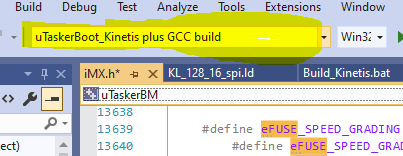
When using VS and its simulation of uTasker projects the "Solution Configuration" drop down (where it shows the target being used) tend to be rather narrow by default and so the target selected is not really visible. It can however be configured to be wider so that it becomes much more useful, as long as it can be worked out how to actually do it.

Here is the method:

1. Hover your mouse over the "Solution Configuration" and press right mouse to see the context menu.


2. Select "Customize..." - right at the bottom.

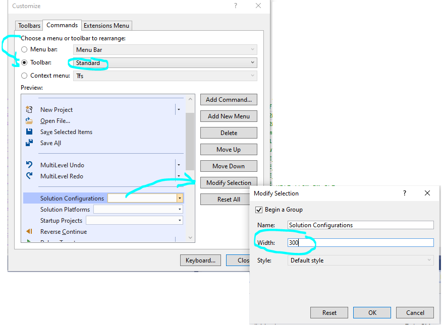
3. Now select the "Standard" Toolbar in the Commands tab and select "Solution Configurations" before commanding "Modify Selection", which gives the possibility to change its width setting:


Regards

Mark

7
NXPTM M522XX, KINETIS and i.MX RT / Kinetis CRC HW Module
« on: February 21, 2021, 06:04:20 AM »
Hi All

The following details concern the CRC HW module in the Kinetis parts and is valid as from 21st Feb. 2021 in the developers version.


1. The driver can be enabled with (in app_hw_kinetis.h) SUPPORT_HW_CRC

2. These are the modes that are  implemented:
CRC16_CCITT_FALSE_CALCULATION
CRC16_AUG_CCITT_CALCULATION
CRC16_CDMA2000_CALCULATION
CRC16_DDS110_CALCULATION 
CRC16_DECTR_CALCULATION   
CRC16_DECTX_CALCULATION   
CRC16_T10_DIF_CALCULATION
CRC16_TELEDISK_CALCULATION
CRC16_XMODEM_CALCULATION 
CRC16_EN_13757_CALCULATION
CRC16_GENIBUS_CALCULATION
CRC16_MAXIM_CALCULATION   
CRC16_TMS37157_CALCULATION
CRC16_MCRF4XX_CALCULATION
CRC16_RIELLO_CALCULATION 
CRC16_USB_CALCULATION     
CRC16_ARC_CALCULATION     
CRC16_MODBUS_CALCULATION 
CRC16_MCRF4XX_CALCULATION
CRC16_RIELLO_CALCULATION 
CRC16_TMS37157_CALCULATION
CRC16_A_CALCULATION       
CRC16_KERMIT_CALCULATION 
CRC16_BUYPASS_CALCULATION
CRC16_X25_CALCULATION     
CRC16_DNP_CALCULATION     
CRC32_IEEE_CALCULATION   
CRC32_BZIP2_CALCULATION   
CRC32_MPEG2_CALCULATION   
CRC32_POSIX_CALCULATION   
CRC32_Q_CALCULATION       
CRC32_C_CALCULATION       
CRC32_D_CALCULATION       
CRC32_JAMCRC_CALCULATION 
CRC32_XFER_CALCULATION


3. In debug.c are some test commands in the I/O menu which allow testing two CRC16 and two CRC32 types to be verified

    {"crc16",             "Check CRC-16-Maxim",                    DO_HARDWARE,      DO_CRC_16_MAXIM},
    {"crc16b",            "Check CRC-16-Buypass",                  DO_HARDWARE,      DO_CRC_16_BUYPASS},
    {"crc32",             "Check CRC-32-IEEE",                     DO_HARDWARE,      DO_CRC_32_IEEE},
    {"crc32m",            "Check CRC-32-Mpeg-2",                   DO_HARDWARE,      DO_CRC_32_MPEG2},

4. This is how to use it (see also the code in debug.c which verifies the result with reference values).

Code: [Select]
              static const unsigned char ucRefData[] = {'1', '2', '3', '4', '5', '6', '7', '8', '9', 'A', 'B'};

              fnCalculateCRC(ucRefData, sizeof(ucRefData), (CRC16_MAXIM_CALCULATION));   // configure the calculation and calculate the first buffer
              fnCalculateCRC(ucRefData, sizeof(ucRefData), 0);           // recalculate without reseeding
              ulCalculated = fnCalculateCRC(ucRefData, sizeof(ucRefData), 0); // recalculate without reseeding
              fnDebugHex(ulCalculated, (WITH_LEADIN | sizeof(unsigned short) | WITH_CR_LF)); // display the result
              if (ulCalculated == 0xf0bc) {                                // recalculate without reseeding and terminate (power down hardware CRC module)
                  fnDebugMsg("Pass\r\n");
              }
              else {                 
                  fnDebugMsg("Failed\r\n");
              }


Terminal output example:

#crc16
0xf0bc
Pass


The example shows the input being passed 3 times.
If one only needs to calculate a single buffer it is used like this:

Code: [Select]
usCalculated = (unsigned short)fnCalculateCRC(ucRefData, sizeof(ucRefData), (CRC16_MAXIM_CALCULATION));

CRC16_MAXIM_CALCULATION selects the standard to use (internally it uses 0x8005 polynomial, 0x0000 seed value and the result is inverted).
The result returned is always 32 bits in length but in the case of the CRC16 (as shown) it can be cast to a 16 bit result.


If the calculation is to be performed over multiple input buffers without resetting the seed in between following calls can be done with:

Code: [Select]
fnCalculateCRC(ucRefData, sizeof(ucRefData), (0)); // continue calculating the CRC over multiple buffers
fnCalculateCRC(ucRefData, sizeof(ucRefData), (0));
usCalculated = (unsigned short)fnCalculateCRC(ucRefData, sizeof(ucRefData), (0)); // use the final result

The mode parameter is simply set to 0 so that the mode is retained without setting a new seed value. Intermediate results are returned but don't need to be used until all buffers have been handled.


5. After each calculation the CRC module is automatically powered down.

6. The API should be very easy to use and can be used for a wide range of standard CRC16 and CRC32 calculations just by passing the desired mode parameter (without needing to know all setup details to achieve the mode)

7. The function works in on the Kinetis HW when it has a CRC module integrated. It also works in the simulator when using this command. The simulator emulates the way that the module operates and produces the equivalent output for all of the modes.


Regards

Mark


8
How to add new CLI menus and commands - valid from check-in 6th February 2021.

1. Add a new line in the table tMainCommand[]

    {"C",                 "Go to My Commands menu",                DO_HELP,          DO_MENU_HELP_MY_COMMANDS},

and add a new define DO_MENU_HELP_MY_COMMANDS (for example, see where the list with DO_MENU_HELP_MQTT is and add it on to there)


2. Search for the way that DO_MENU_HELP_MQTT is handled:

        else if (DO_MENU_HELP_MQTT == ucType) {
            ucMenu = MENU_HELP_MQTT;                                     // set MQTT menu
            return (fnDisplayHelp(0));                                   // large menu may require special handling
        }


and add a new help handler for your new sub-menu:

        else if (DO_MENU_HELP_MY_COMMANDS == ucType) {
            ucMenu = MENU_HELP_MY_COMMANDS;                                     // set my new menu
            return (fnDisplayHelp(0));                                   // large menu may require special handling
        }


Locate MENU_HELP_MQTT (it is an enum in versions from 6th Feb. 2021) and extend the list with MENU_HELP_MY_COMMANDS (this must be in the enum list menu_help_reference in the same order as the main menu is built up!!!!!).


3. Add a new line in the table

ucMenus[]

eg.

{ tMyCommands,          15, (sizeof(tMyCommands)/sizeof(DEBUG_COMMAND)),          "    My menu"},

Note that the value 15 is the tab spacing when listing commands in this menu. 15 tends to be fine but it can be increased if you have long commands in the menu (which are added next). See reference at the end to see what the TAB SPACING affects.


4. This then needs its own sub-menu (tMyCommands)

Start with

static const DEBUG_COMMAND tMyCommands[] = {
    {"up",                "go to main menu",                       DO_HELP,          DO_HELP_UP},
    {"help",              "Display menu specific help",            DO_HELP,          DO_MAIN_HELP},
    {"quit",              "Leave command mode",                    DO_TELNET,        DO_TELNET_QUIT},
};

so it supports basic help, quit and up commands.

This should already run, showing a sparse new sub-menu


5. To add a new command insert one in to the tMyCommands[] table

    {"new_command",              "Description",                  DO_MY_GROUP,      DO_MY_COMMAND},

where you need to add new defines

DO_MY_GROUP (see where the list with DO_TELNET is and add it to there)

DO_MY_COMMAND (start a new list of defines dedicated to the new sub-menu - eg. beginning with 1)

You can also use existing groups (such as DO_TELNET) if you want to handle the new command type there rather than creating a new group.


6. Make a group action handle (assuming a new group define was added) where the new command is handled - starting an action, with or without interpreting additional parameters passed in the ptrInput string)


static void fnNewGroup(unsigned char ucType, CHAR *ptrInput)
{
    switch (ucType) {
    case DO_MY_COMMAND:
        // Handle the command here
        break;
    }
}


and enter it in


static int fnDoCommand(unsigned char ucFunction, unsigned char ucType, CHAR *ptrInput)

{
...
    case DO_TELNET:                  <----example of existing group handler
        fnDoTelnet(ucType, ptrInput);
        break;
...
    case DO_MY_GROUP:         <--- the new group handler
        fnNewGroup(ucType, ptrInput);
        break;

...
}


Now the new sub-menu exists, can be entered and exited and one new command is available. When the command is executed the DO_MY_COMMAND case is hit and the specific new command code can be added there.


     Main menu
===================
N [TAB SPACING]Configure network
S              Configure serial interface
I              Go to I/O menu
A              Go to administration menu
O              Go to overview/statistics menu
U              Go to USB menu
M              MQTT client commands
C              Go to My Commands menu
help           Display menu specific help
quit           Leave command mode
C


     My menu
===================
up             go to main menu
new_command    Description
help           Display menu specific help
quit           Leave command mode

#new_command


To extend existing sub-menus with new commands just step 5. can be used to extend existing menus and no new group is usually needed.

Regards

Mark


9
Hi All

The i.MX RT 106x parts include high-speed ports that are clocked at the core's clock speed and tightly coupled for fastest control.

This video shows the speeds that the GPIOs can achieve and gives additional background concerning their implementation and use:
https://youtu.be/nLInUIboLR0

Regards

Mark

10
NXPTM M522XX, KINETIS and i.MX RT / Teensy 4.1 with Ethernet Kit
« on: December 26, 2020, 12:23:28 AM »
Hi All

Guess what I received for Christmas?

A Teensy 4.1 with Ethernet Kit !!!

So I soldered the Ethernet Kit together and built the uTasker Loader and an application with Ethernet features as found here: https://www.utasker.com/iMX/Teensy_4_1.html

I did have to adapt the PHY configuration slightly to ensure it was configured to match the HW's clocking but then it started working as it should.

Regards

Mark

11
Preview of some new feature in the uTasker projects uGLCDLib supporting rich graphics and touch control completely in internal RAM, with i.MX RT processor, peripheral, interrupt, DMA, TFT and touch controller simulation for easy developing which makes embedded processing quick and fun to do!

https://youtu.be/83-Sc4TqpSc

Regards

Mark

12
Hi All

See this video for explanation!

https://youtu.be/5iT7KP691ls

Regards

Mark

13
NXPTM M522XX, KINETIS and i.MX RT / i.MX RT XBAR + AOI modules introduced
« on: September 03, 2020, 03:42:08 AM »
Hi All

New video showing XBAR and AOI in operation:
https://youtu.be/zNWIG-O7ZW0

Regards

Mark

14
Hi All

This new guide shows how combining the uTasker Serial Loader with the "Bare-Minimum Loader can allow serial loader updates with a code size overhead as low as 2k Bytes:

https://www.utasker.com/docs/uTasker/uTaskerSerialLoaderUpdater.pdf

Regards

Mark

15
NXPTM M522XX, KINETIS and i.MX RT / i.MX RT Playlist
« on: May 04, 2020, 04:22:18 AM »
Hi All

Finally I have got to the point that my time is not consumed fully by new i.MX RT development and the new support can be well demonstrated.

To get the ball rolling I have created a new playlist on Youtube "uTasker i.MX RT"

https://www.youtube.com/watch?v=GXztWg9m6_8&list=PLWKlVb_MqDQEOCnsNOJO8gd3jDCwiyKKe

This starts with an introduction to the i.MX RT to give a foundation for future more technically details videos discussing more specific i.MX RT / uTasker topics. The next one will probably be the extended uTasker boot loader concept (secured as standard) now available in the i.MX RT version.

I believe that the results make the chips easier to use and manage (in production and in firmware maintenance once products have been shipped) and am hoping for its use to take off.

The i.MX RT devices are powerful and flexible and so the support journey is gong to be a long one, but fruitful.

If there are burning i.MX RT topics that someone thinks merits its own video please suggest here!

Regards

Mark

Pages: [1] 2 3 ... 19